Getting Started with ATLAS 3D
The following content instructs the user on how to assembly, calibrate, and scan with ATLAS 3D.
Software Install (BYOP ONLY)
Note: This step is for BYOP Kit backers only. All other kits have the software pre-installed on the SD card.
An ATLAS 3D software image is provided to make it easier for BYOP Kit backers to get up and running. It is located at https://s3.amazonaws.com/atlas3d/2015-05-01-atlas3d.zip. An 8GB or larger SD card is required. Instructions for writing the image to an SD card can be found at https://www.raspberrypi.org/documentation/installation/installing-images/.
Scanner Assembly
The following video shows how to assembly the ATLAS 3D scanner step by step. Printed instructions are included with the kit.
Determining the Scanner's IP Address
In order to connect remotely to the scanner, the IP address of the scanner must be determined. This is most easily done by attaching a monitor, keyboard, and mouse to the HDMI and USB ports. Once prompted for login information enter the following:
If you are doing a wired connection to the scanner, insert the Ethernet cable and type the following command at the prompt.
The IP address of the scanner should be listed after the inet addr: for eth0. For example: 192.168.0.201. If you are connecting over Wifi, plug in the Wifi adapter and follow the instructions at Raspberry Pi Wifi Configuration. Type the following command at the prompt.
The IP address of the scanner should be listed after the inet addr: for wlan0.
NOTE: Depending upon how your home network is setup, you may be able to simply enter http://atlas3d/ (no .com) instead of the IP address.
Connecting to the Scanner
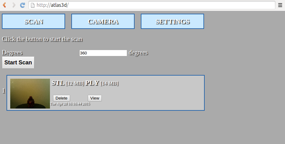
Once the IP address is known, enter it into a web browser on the same network. For example, if the IP address is 192.168.0.6 you would enter http://192.168.0.6/ in the location bar of the web browser. You may be able to simply enter http://atlas3d/. The main interface for the scanner should come up at this point.
Register the Scanner
Register your ATLAS 3D scanner with the included 8 character serial number at https://www.murobo.com/register.php. The serial number is located on the bottom of the stepper motor. Then, enter the serial number on the Setup page by navigating to SETTINGS and then clicking Setup. This will allow the scanner to receive software updates.
Hardware Calibration
This video below shows how to calibrate an ATLAS 3D scanner.
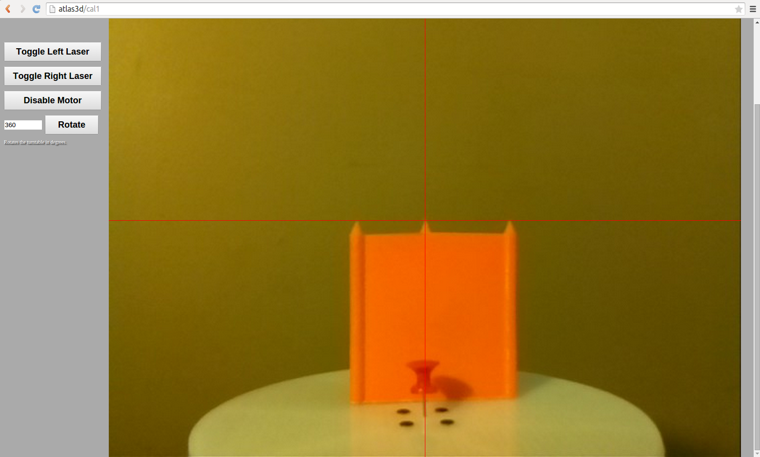
Before scanning for the first time, the hardware must be calibrated. Calibration is the process of moving the lasers and camera to the orientations that the software expects. The Calibration Item Model must be printed and used for the process. Calibration is performed from the Camera page.
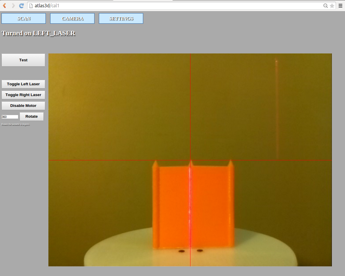
The first step in calibration is aligning the the camera.
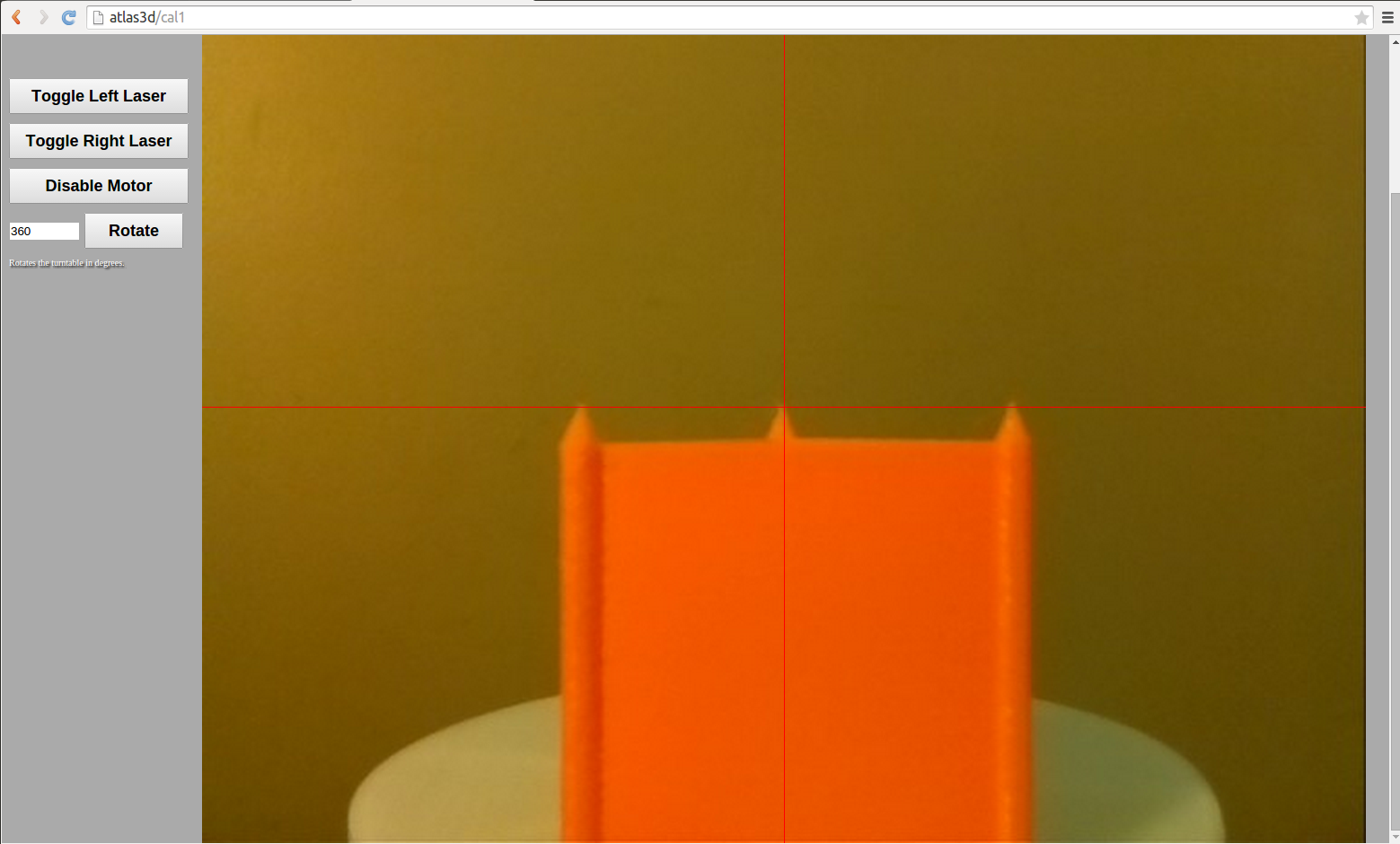
The next step is to calibrate the lasers.

Getting Good Scans
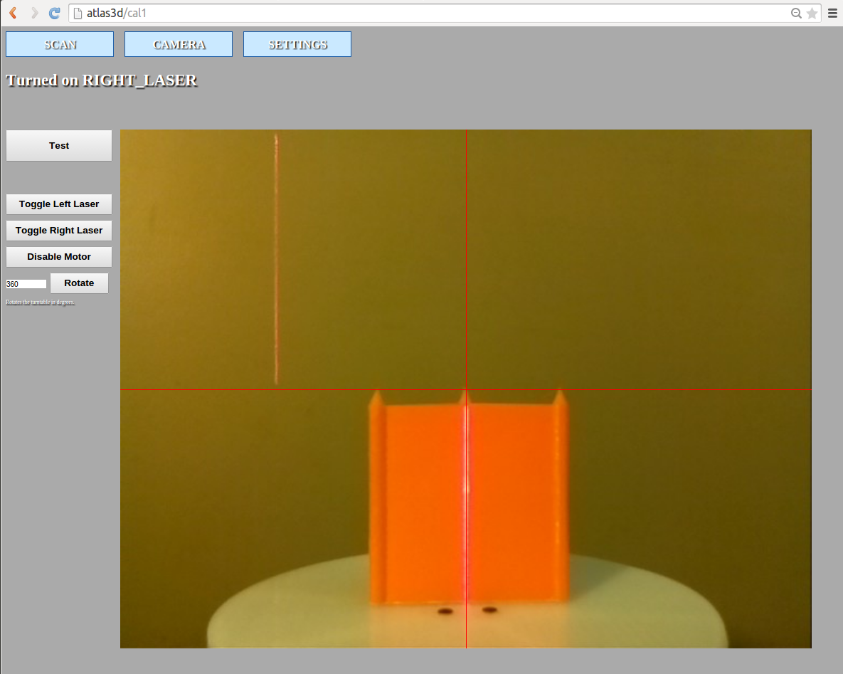
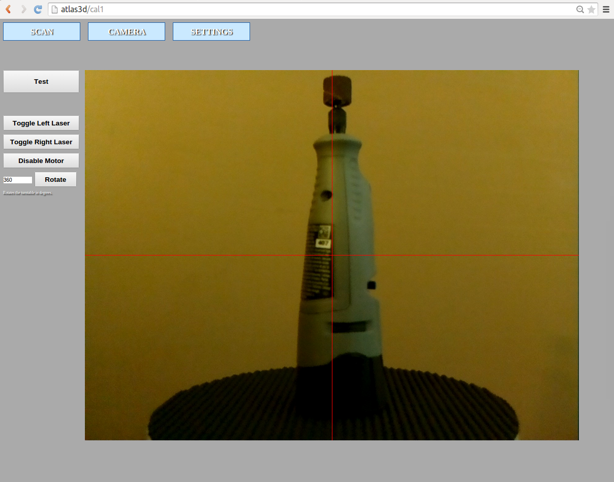
Once calibration is complete, the next most important part of getting good scans is balancing the lighting with the laser threshold setting. If the light is too bright then it will over saturate the laser line and make it difficult for the camera to pick it up. If the light is too dim the camera image will be noisier, the laser will appear to reflect off the object more, and the resulting scan will be much darker than the object. Before scanning an object, first select the Preset that you would like. Navigate to the CAMERA page and click the test button. Suppose we are scanning the object below...
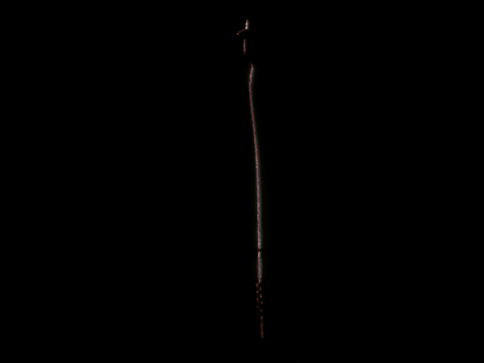
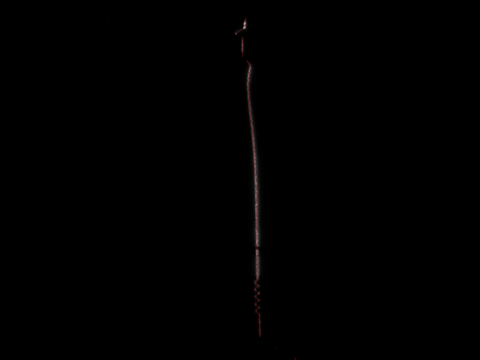
Click the Test button to see if the current settings and lighting is appropriate for the object. The image below shows the resulting test image. The test image shows the detected laser line after processing the image from the camera. The gray pixels are those that are above the threshold value, while those below the threshold are yellow. The red line shows where the center of the laser was detected. To obtain a good scan, there must be a red line everywhere that the laser contacts the object. For this to occur, the threshold settings must be set appropriately. If the threshold value is too high (or there is too much direct light) then there will be gaps in the object. If the threshold value is too low then laser detection false positives can occur in the background pixels resulting in scans with lots of points floating around off the object. In the image below notice the gaps toward the bottom of the image.
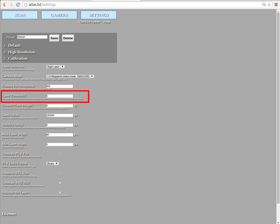
We can correct for this by lowering the laser threshold value. The laser threshold value is close to the top of the SETTINGS page. Lower the value by half, save the preset, and generate another test image.
With the new laser threshold setting there is now a much better line at the bottom of the image. The object is not ready to be scanned. From the SCAN page click Start Scan to scan the object.
Once the scan is complete, click on the file link (STL, PLY, etc) to download it from the scanner.
Support Forum
Support can be found on the ATLAS 3D forum at http://www.soliforum.com/forum/29/atlas-3d-freelss/.